Temperature sensors with display and alerting for marine aquarium
In marine fishkeeping, maintaining the correct water temperature is crucial for the health of both fish and corals. Marine life thrives in a temperature range of 23 to 28 °C. Water temperature is heavily influenced by factors like room temperature, UV-C clarifiers, and especially lighting systems like LEDs, particularly when they are installed close to the water surface. If the water temperature moves outside of the optimal range, it can cause serious harm or even death to both fish and corals.
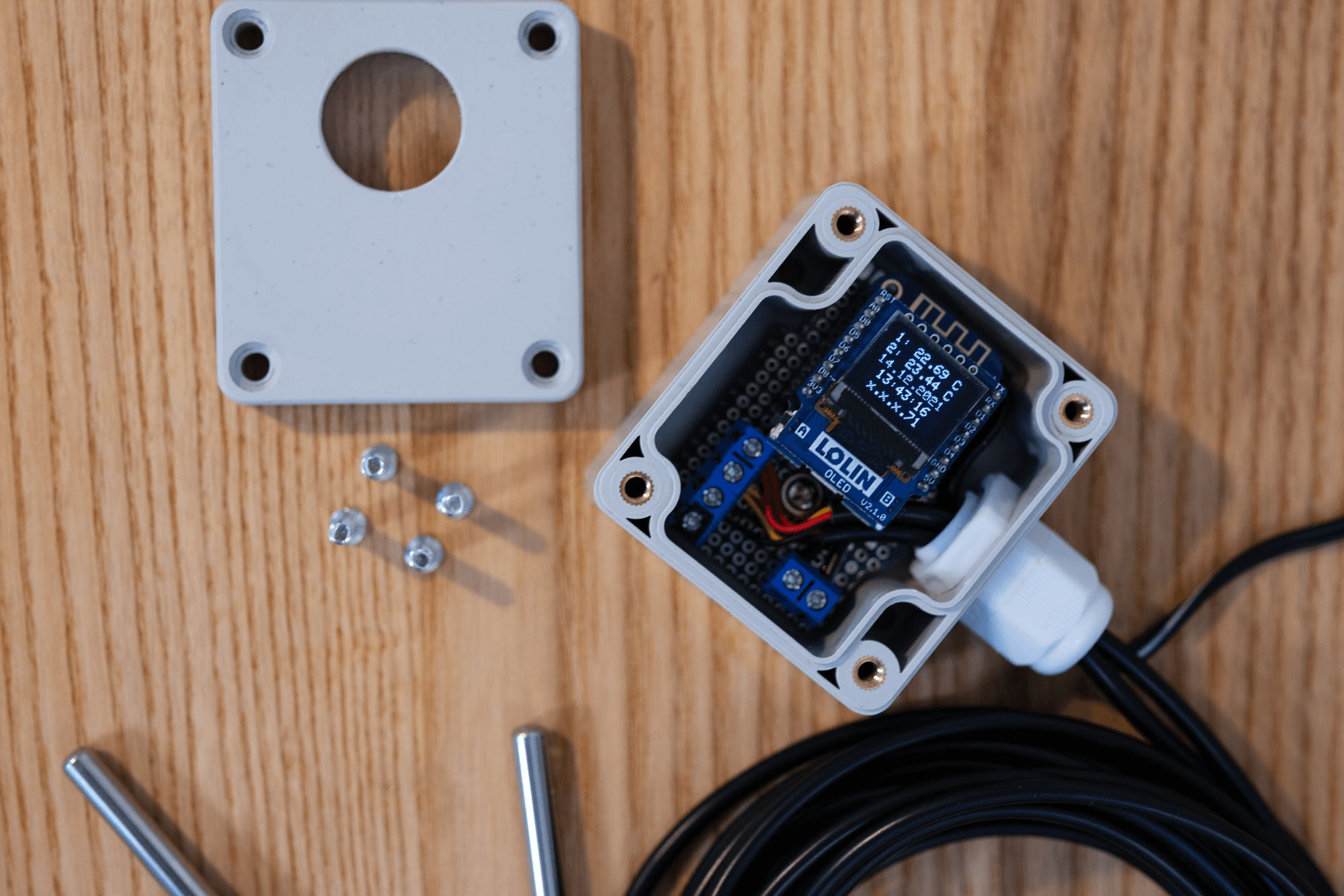
To prevent such occurrences, I designed and built a small, standalone device that constantly monitors the water temperature at two different points in the aquarium. This device has a built-in display to check the current temperature directly, without needing a mobile phone. The device also includes alerting features, both visual and auditory, which notify you if the temperature moves outside a defined range of 24-27 °C. In case the temperature exceeds 28 °C, the device will notify you through a physical buzzer and a flashing display. A snooze button is also provided to pause the notifications for a set period of time.
Why is Temperature So Important in Marine Aquariums?
The ideal water temperature for marine aquariums is between 23 and 28 °C. Temperatures above 28 °C are critical because at this point, the aquarium starts to leave the optimal range, and prolonged exposure can lead to stress in fish and corals. At 29.5 °C, the situation becomes even more dangerous, risking serious harm or death to the inhabitants.
Device Features
The device is designed to be reliable and maintenance-free. It operates with a power supply (no batteries) and uses two temperature sensors to measure the water temperature continuously. A closed housing protects it from the corrosive saltwater environment.
In addition to the local display, the device integrates with a home automation system (HomeMatic) via MQTT, allowing for remote monitoring. Temperature data is also logged in an InfluxDB database for detailed trend analysis using Grafana. This is crucial for long-term monitoring, as it helps detect patterns and prevent future temperature spikes. Notifications are also sent via Pushover, with alerts every 10 minutes if the temperature exceeds the critical 28 °C threshold.

Device Specifications
- Temperature Sensors: Two sensors to monitor different points in the aquarium.
- Display: A small OLED display (64x48 pixels) shows the following information:
- Temperature from Sensor 1: e.g., “1: 23.00 °C”
- Temperature from Sensor 2: e.g., “2: 24.00 °C”
- Last update timestamp: e.g., “30.11.2021 12:05:59”
- IP address of the device: e.g., “x.x.x.123”
- MQTT Communication: The following data is sent to an MQTT broker for remote monitoring:
- /data/aquarium/temp/1 = 23.00 °C
- /data/aquarium/temp/2 = 24.00 °C
- /data/aquarium/temp/updated = 2021-12-01 12:05:59
The MQTT broker integrates with HomeMatic for remote control and logging to an InfluxDB database for graphical analysis in Grafana. This allows you to track temperature changes over time and react before problems arise.
Building the Device
Now lets have a look at the list of part I used:
| ## | Parts | Amazon.de |
|---|---|---|
| 1 | 1 x D1 Mini D1 Mini V3 NodeMCU ESP8266EX | Amazon-Link |
| 2 | 1 x OLED display shield I2C SSD1306 | Amazon-Link |
| 3 | 2 x Temperature Sensor - 3M Kabel DS18B20 | Amazon-Link |
| 4 | 1 x Box, Electronic Enclosure, Waterproof (89x59x35mm) | Amazon-Link |
| 5 | 1 x Round Acryl Sheets, 2 Zoll/ 5 cm | Amazon-Link |
| 6 | 1 x UHU 45440 Superglue | Amazon-Link |
| 7 | 1 x M12 Cable Fitting | Amazon-Link |
| 8 | 1 x KY-012 Piezo Buzzer Alarm | Amazon-Link |
| 9 | 1 x Resistor 470Ω from Resistor Kit | Amazon-Link |
| 10 | 1 x Resistor 10kΩ from Resistor Kit | Amazon-Link |
| 11 | 1 x PCB 7x3cm shortened from Universal Board Kit | Amazon-Link |
| 12 | 3 x Screw Terminals from Universal Board Kit | Amazon-Link |
| 13 | 1 x Tactile Push Button 9,5mm from Button Kit | Amazon-Link |
| 14 | 1 x Micro Cable Electronics Male/Female Connector | Amazon-Link |
| 15 | 1 x Universal Power Supply 5V | Amazon-Link |
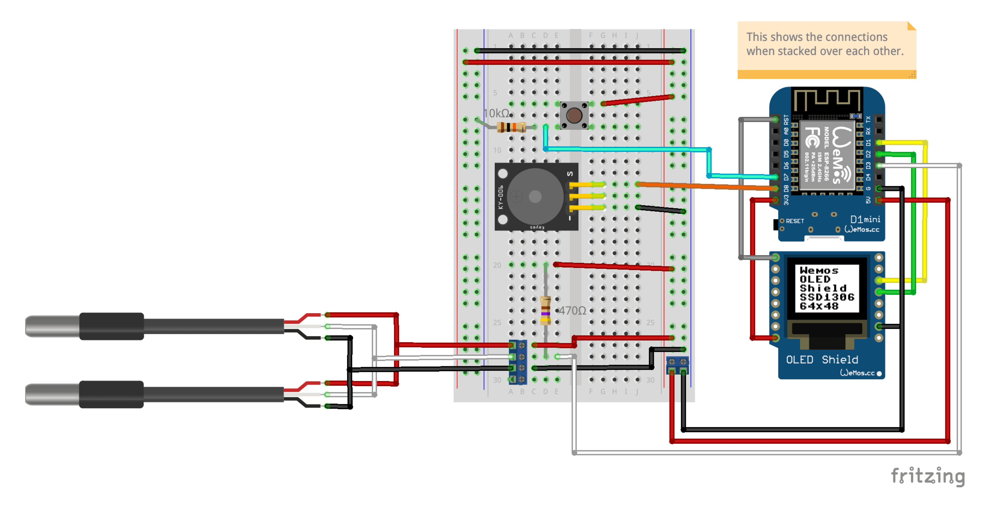
I used the tool Fritzing to desing the circuite. Afterwards I cut out a board and soldered all parts on it so that it fits into the small case.

Source Code
The source code of the PlatformIO project can be found on Github:
Software and Libraries
I used the ESPDateTime library to sync the time with an NTP server and PlatformIO for VSCode development. You can also find the ESP Board Manager URLs for your setup here:
ESP8266: http://arduino.esp8266.com/stable/package_esp8266com_index.json
For more details on Wemos D1 Mini boards, you can check out Wolles Elektronikkiste.